www.gokartsupply.com


Go Kart Steering Parts

Tie Rods and Tie Rod Ends

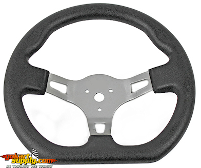
Steering Wheel-Steel
Go Kart Steering Wheels
SKU
Description
Price
Add to Cart
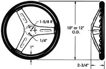
10" STEERING WHEEL
42.50

12" STEERING WHEEL
46.50

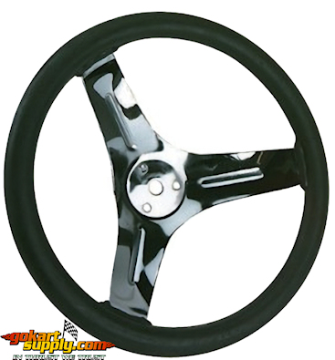
1/2" Center Hole, (3) 1/4" Mounting Holes that measure 1-3/8" Center to Center. One Piece Chrome Plated Steel, Solvent-Proof Neoprene, Molded Finger Grooves. Go Kart Steering Wheel.
Butterfly Steering W
Butterfly Steering Wheel
SKU
Description
Price
Add to Cart
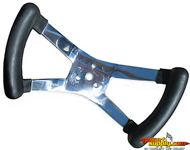
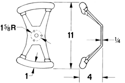
BUTTERFLY STEERING WHEEL
64.50

1/2" Center Hole, (3) 1/4" Mounting Holes that measure 1-3/8" Center to Center. One Piece Chrome Plated Steel, Solvent-Proof Neoprene, Molded Finger Grooves. Go Kart Steering Wheel.
SW Cap
Chrome Plated
Steering Wheel Cap
SKU
Description
Price
Add to Cart
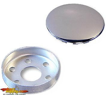
STEERING WHEEL CAP CHROME
14.50

Steel, Chrome Plated Steering Wheel Cap Assembly. Fits 1-1/2" or 1-5/8" Bolt Hole Circle. Fits Steering Wheel Part Number 04-5890, 04-9396 and 2294. (Steering Parts)
ASW Steering Wheel
Go Kart Steering Wheel
SKU
Description
Price
Add to Cart
STEERING WHEEL 3170,3171,
26.50

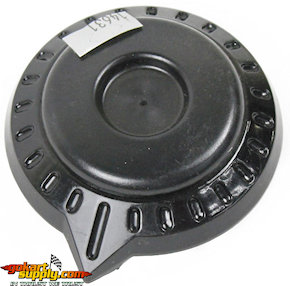
Go Kart Steering Wheel. Fits American Sportworks Model 3170B-09 Hornet, 3170B-11 Dragonfly, 3171B-09 Black Widow, 3171B-25 Black Widow and 4170 Fox Vector Go Karts. Hammerhead Mudhead / Torpedo Steering Wheel for Mid Size and Mini Size Go Karts. American Sportworks 14632 - American Landmaster 14632 - Hammerhead Part 7.020.057 - Trailmaster 7020057080G000
ASW Steer Whl Cap
Steering Wheel Cap
SKU
Description
Price
Add to Cart
STEERING WHEEL CAP
5.50

Fits Steering Wheel 14632 and 115539.
Steering Wheel Adapt
Steering Wheel Adapter
SKU
Description
Price
Add to Cart
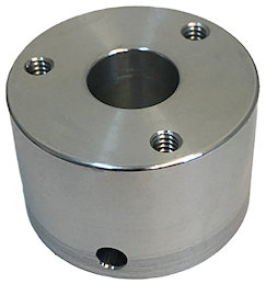
STEERING WHEEL ADAPTER
27.50

Fits all Steering Wheels above to a 3/4" Shaft with 1/4" Cross-Drilled hole. Fits Steering Wheel Part Number 04-5890, 04-9396, 2294 and 14632. Hardware not included. Use with Hardware Kit Part #116657, 116658 or 116659 (sold below). Made in the USA.
Standard Bolt Kit
S.W.A. Bolt Kit
G20300 Standard
SKU
Description
Price
Add to Cart
116657
BOLT KIT - G20300 STD
2.99

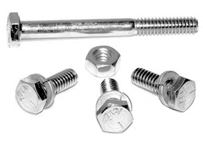
Standard Bolt Kit for Steering Wheel Adapter Part #G20300. Contains all hardware required to attach steering wheel and adapter to 3/4 inch steering shaft with 1/4 inch cross drilled hole.
Flange Lock Bolt Kit
S.W.A. Bolt Kit
G20300 Flange Lock
SKU
Description
Price
Add to Cart
116658
BOLT KIT - G20300 FLG LOCK
3.49

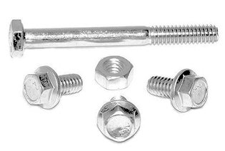
Flange Lock Bolt Kit for Steering Wheel Adapter Part #G20300. Contains hardware required to attach steering wheel and adapter to 3/4 inch shaft with 1/4 inch cross-drilled hole. Flange lock bolts lock without washers providing a more decorative appearance.
Socket Head Bolt Kit
S.W.A. Bolt Kit
G20300 Socket Head
SKU
Description
Price
Add to Cart
116659
BOLT KIT - G20300 SKT HEAD
3.99

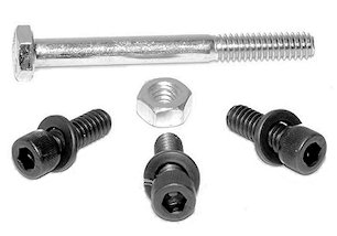
Socket Head Bolt Kit for Steering Wheel Adapter Part #G20300. Contains hardware required to attach steering wheel and adapter to 3/4 inch shaft with 1/4 inch cross drilled hole. Black Steel socket head bolts and washers provide a decorative appearance which contrasts well with chrome or silver steering wheels.
Steering Shafts 5/8
5/8" Steering Shaft Kit
SKU
Description
Price
Add to Cart
STEERING SHAFT KIT 28"
46.50

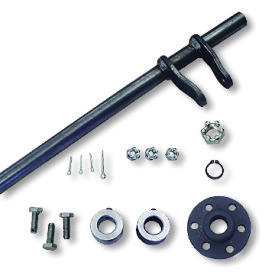
5/8" Steering Shaft Kit with Welded Pitman Arms.
1873 Steering Hardware
Steering Shaft Hardware Kit
SKU
Description
Price
Add to Cart
STEERING SHAFT HARDWARE KIT
24.50

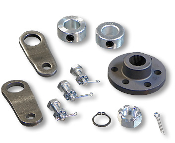
Go Kart Steering Shaft Hardware Kit, Less Shaft, with Pitman Arms. Pitman Arms for 5/8" OD Steering Shaft, 5/8" Shaft Hole, 5/16" Bolt Hole, 5 GA. (.21O"), 1-5/8" Center to Center with 3/16" Offset. Hub, Splined for 5/8" OD Steering Shaft, 2 Bolt Circles. Three 1/4-28 X 3/4" Bolt, 1/16" Hole drilled 3/32" from end. 3/32" X 3/4" Cotter Pin, 1/16" X 1/2" Cotter Pin, 1/4-28 Slotted Hex Nut, 1/2-20 Slotted Hex Nut, Two 5/8" ID X 1-1/8" OD X 1/2" wide Lock Collars. Hardware Zinc Plated.
Tie Rods
3/8" Tie Rods
For American Go Karts
SKU
Description
Price
Add to Cart
TIE ROD 6 INCH 3/8-24X2.25
8.50

TIE ROD 8 INCH 3/8-24X2.25
9.50

TIE ROD 10 INCH 3/8-24X2.25
9.50

TIE ROD 12 INCH 3/8-24X2.25
10.50

TIE ROD 14 INCH 3/8-24X2.25
10.50

TIE ROD 16 INCH 3/8-24X2.25
12.50

TIE ROD 18 INCH 3/8-24X2.25
14.50

TIE ROD 19 INCH 3/8-24X2.25
14.50

TIE ROD 20 INCH 3/8-24X2.25
16.50

TIE ROD 25 INCH 3/8-24X2.25
16.50

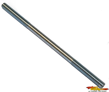
3/8" Tie Rods with Right and Left Hand Threads for easy adjustment. Left hand thread on one end, right hand thread on the other. Requires both right and left hand jam nuts and tie rod ends. There's 2-1/4" of thread on each end. Can be cut down 1" to shorten the rod by up to 2". Fits American Made Go Karts. Can be used with STANDARD and DELUXE Tie Rod Ends.
Jam Nuts for Tie Rod
3/8" Jam Nuts
SKU
Description
Price
Add to Cart
JAM NUT 3/8-24 RIGHT HAND
1.50

JAM NUT 3/8-24 LEFT HAND
1.50

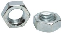
Jam Nuts for 3/8" Tie Rods. Thin, Fine Thread, 3/8-24 Jam Nuts. Available in Left Hand Thread or Right Hand Thread. Used on American Made Go Karts with 3/8" Tie Rods.
Deluxe Tie Rod Ends
Deluxe 3/8" Tie Rod Ends
Right or Left Hand Thread
SKU
Description
Price
Add to Cart
3/8" RH DELUXE ROD END
9.50

3/8" LH DELUXE ROD END
9.50

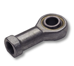
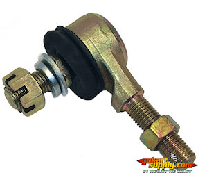
DELUXE 3/8" Tie Rod Ends.
Used on American Go Karts with 3/8" Tie Rods.
Can be used to replace STANDARD Tie Rod Ends.
Manco Tie Rod Ends
3/8" Right Hand or Left
Hand Female Tie Rod Ends
SKU
Description
Price
Add to Cart
3/8" LEFT HAND THREAD ROD END
9.50

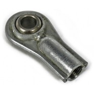
STANDARD 3/8" Tie Rod Ends.
Used on American Go Karts with 3/8" Tie Rods.
Ball Joints
Right Hand Thread Rod Ends
SKU
Description
Price
Add to Cart
5/16" 24 RH THREAD ROD END
7.50

3/8" 24 RH THREAD ROD END
10.50

Left Hand Thread Rod Ends
3/8" 24 LH THREAD ROD END
10.50

Tie Rod Assy 14637
American Sportworks
14637 Tie Rod Assembly
SKU
Description
Price
Add to Cart
TIE ROD 14637
52.50

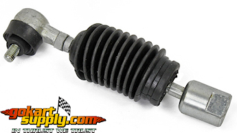
Fits American Sportworks Go Kart Model 3170 Hornet and Dragonfly, 3171 Black Widow Go Karts, 4170 Vector and 5210 Marauder Go Karts. Assembly includes: 1 Tie Rod, 1 Dust Cover Boot and 1 Tie Rod End. American Sportworks 14637 American Landmaster 14637
62610-132-0000 Ball Joint
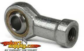
8mm Tie Rod End w/ Ball Joint
Coleman KT196 & HiSun HS200GK
SKU
Description
Price
Add to Cart
62610-132-0000
STEERING MECHANISM BALL JOINT
15.50

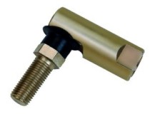
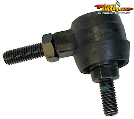
Steering Mechanism Ball Joint. Rod End with 8mm Threads. 8mm x 1.25 x 17mm Standard Threads on the Ball Joint Stud. 8mm x 1.25 x 23mm Left Hand Thread on the Fixed Stud. Total Length: 65mm [2.57"] Fixed Side. Total Height: 51mm [2.01"] Ball Side. Used on Coleman KT196 Go Karts, HiSun HS200GK Go Karts, Hammerhead Mini's, Hammerhead Shark Go Karts, Hammerhead 80T Go Karts and Trailmaster Mini and Mid-Size Go Karts. Hammerhead Part # 6.000.181 - Trailmaster # 6000181080G000, Coleman Part # 430-BJ441-112, Part #64130-400001-0000 and Coleman # 62610-132-0000
Rod End 6.000.062
10mm Tie Rod Ends
SKU
Description
Price
Add to Cart
6.000.062
10MM TIE ROD END
19.50

Used on 150cc Hammerhead Go Karts.
Tie Rod End 14529 RH
10mm Right Hand
Thread Tie Rod End
SKU
Description
Price
Add to Cart
TIE ROD END 10MM RH
12.88


Go Kart Wheel Alignment

Basic 'Toe In' Instructions


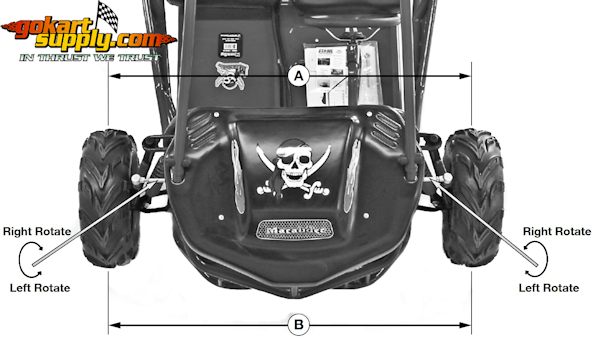
The front wheels should be set with a 'Toe-In' from 1/4 inch to 1/2 inch. At the centerline of the tires, with the wheels pointed straight ahead, measure the Distance A and the Distance B. For proper toe adjustment, Dimension A should be a 1/4 inch to 1/2 inch greater than Dimension B. If dimension A is not 1/8 inch to 1/4 inch greater than dimension B, the front wheels require alignment.

TO MAKE ADJUSTMENTS: Loosen the lock nuts on both sides of Front Tie Rods. Ensure the steering wheel is centered, and adjust Dimension B by equally rotating the tie rods in or out with a wrench.

After adjusting to the desired length, tighten the lock nuts against the Tie Rods.

Recheck the dimensions for proper alignment.

When the steering arm on the steering column is vertical and centered, the front wheels are to be aligned directly forward (not turned). If the wheels are turned when the steering arm is vertical, the steering angle either to the right or left is reduced and the wheels require alignment.
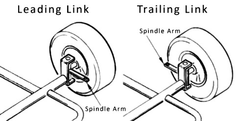

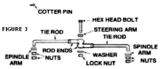
LEADING LINK ALIGNMENT: If the vehicle is equipped with tie rods as shown in Figure 3, adjust as follows: Remove the nuts from both rods at the spindle arm. Loosen and move the jam nut away from both rod ends. To make dimension B smaller, screw both rod ends inward 1 or 2 turns. If B needs to be larger, screw the rod ends outward. Tighten both jam nuts tightly against the rod ends. Replace tie rods in spindle arm and replace nuts. Tighten nuts securely. BOLTS AND NUTS MUST BE IN PLACE AND TIGHT BEFORE CHECKING THE DIMENSIONS. Recheck the distance and repeat the above steps until the dimensions are per instructions above.

Your Kart's Rod Ends may be
different than those illustrated.

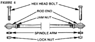
If it's equipped with tie rods as shown above in Figure 4, adjust as follows: Loosen and move the two jam nuts away from the rod ends. To make diminsion B smaller, screw both ends inward on both rods 1 or 2 full turns. If B needs to be larger, screw the rod ends outward. Tighten the jam nuts snugly against the rod ends. Replace the hex head bolts thru the rod ends and spindle arms, and replace the lock nuts. Tighten securely. BOLTS AND NUTS MUST BE IN PLACE AND TIGHT BEFORE CHECKING THE DIMENSIONS. Recheck the distance and repeat the above steps until the dimensions are per paragraph 1 and 2.

TRAILING LINK ALIGNMENT (as shown in Figure 2): If the vehicle is equipped with tie rods as shown in Figure 2, adjust as follows: Remove the nuts from both rods at the spindle arm. Loosen and move the jam nut away from both of the rod ends. To Make dimension B smaller, screw both rod ends out-ward 1 or 2 full turns. If B needs to be larger, screw the rod ends inward. Tighten securely. BOLTS AND NUTS MUST BE IN PLACE AND TIGHT BEFORE CHECKING THE DIMENSIONS. Recheck the distance and repeat the above steps until the dimensions are per paragraph 1 and 2.

If the vehicle is equipped with tie rods as shown above in Figure 4, adjust as follows: Loosen and move the two jam nuts away from the rod ends. To make diminsion B smaller, screw both ends inward on both rods 1 or 2 full turns. If B needs to be larger, screw the rod ends outward. Tighten the jam nuts snugly against the rod ends. Replace the hex head bolts thru the rod ends and spindle arms, and replace the lock nuts. Tighten securely. BOLTS AND NUTS MUST BE IN PLACE AND TIGHT BEFORE CHECKING THE DIMENSIONS. Recheck the distance and repeat the above steps until the dimensions are per paragraph 1 and 2.